


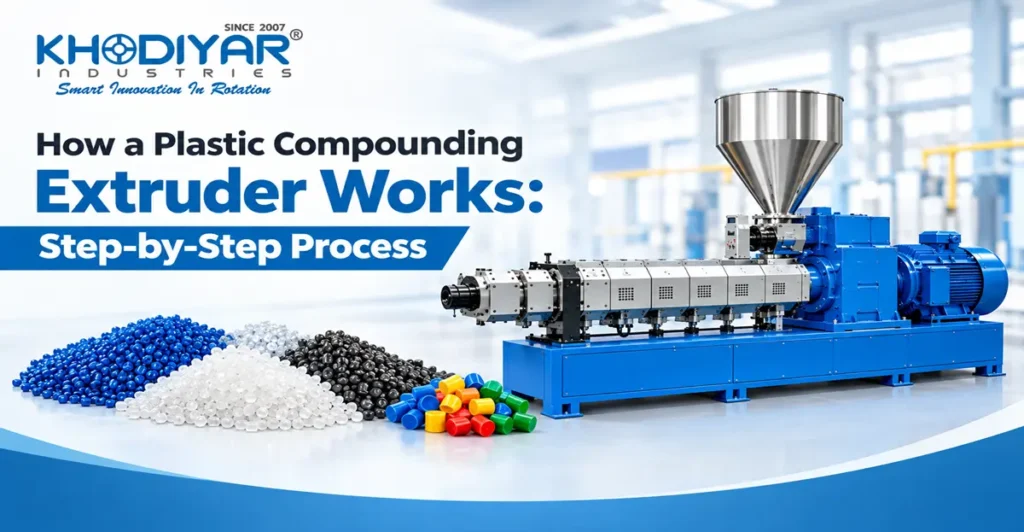
Almost no plastic product is made from virgin polymer alone. Before resin reaches an injection moulding machine, a rotomoulding oven or a pipe extrusion line, it usually passes through a compounding extruder – the machine that blends base polymer with fillers, pigments, stabilisers and modifiers, then converts that mixture into uniform pellets.
Understanding how a plastic compounding extruder works is a commercial question, not just a technical one. The same formulation can produce excellent pellets or unusable ones depending on screw configuration, feeding accuracy, barrel temperature profile and venting. This guide follows the material through the machine – from the hopper to the pellet bag – and explains what controls quality at every stage.
What Is a Plastic Compounding Extruder?
A conventional plastic extruder shapes material. It pushes molten polymer through a die to produce a finished profile – a pipe, a film, a sheet or a cable coating. The output is a product.
A plastic compounding extruder makes a material. Its output is not a finished article but a pellet: a uniform, modified feedstock that other machines will later convert into products. Compounding is therefore a formulation process, and its success is measured by consistency rather than by shape.
| Aspect | Ordinary plastic extrusion | Compounding extrusion |
| Purpose | Shape polymer into a profile | Create a modified material formulation |
| Output form | Pipe, film, sheet, profile | Pellets or granules |
| Die function | Defines the final product geometry | Forms strands only, for cutting into pellets |
| Success measured by | Dimensional accuracy, surface finish | Homogeneity, dispersion, repeatability |
| Next step | Cutting, coiling, packing | Injection moulding, rotomoulding, extrusion, blow moulding |
In practical terms, every pellet in a 25 kg bag should carry the same filler loading, the same pigment concentration and the same additive package as every other pellet. That is the entire job of the machine.
Main Parts of a Plastic Compounding Extruder
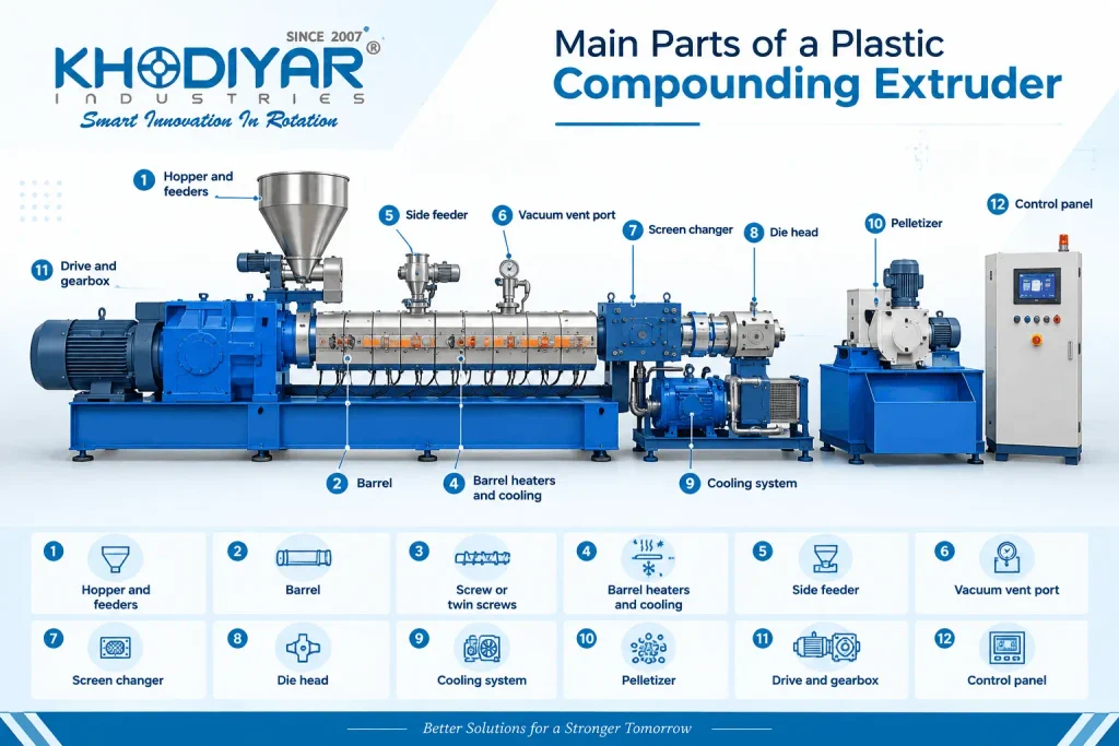
Before following the process, it helps to know what the material passes through.
| Component | Function |
| Hopper and feeders | Hold and meter the base polymer and additives into the machine at a controlled rate |
| Barrel | The heated cylinder in which the material is conveyed, melted and mixed |
| Screw or twin screws | Convey, compress, melt, mix and pressurise the material; the single most important element in compounding |
| Barrel heaters and cooling | Divide the barrel into independently controlled temperature zones |
| Side feeder | Introduces fillers and reinforcements downstream, after the polymer has begun to melt |
| Vacuum vent port | Removes trapped air, moisture and volatiles from the melt |
| Screen changer | Filters contamination and unmelted particles before the die |
| Die head | Forms the melt into continuous strands of even diameter |
| Cooling system | Solidifies the strands using a water bath, water spray or air |
| Pelletizer | Cuts the solidified strands into pellets of uniform length |
| Drive and gearbox | Delivers the torque required to turn the screws under load |
| Control panel | Sets and monitors temperature, screw speed, feed rate, torque and melt pressure |
The Compounding Process at a Glance
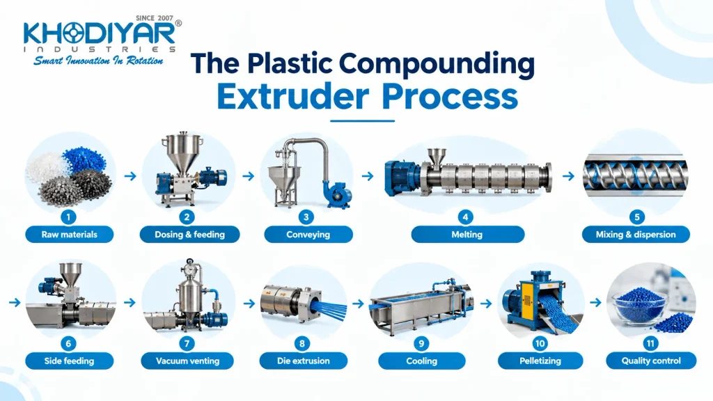
The complete journey of the material can be summarised in eleven stages:
Raw materials → Dosing & feeding → Conveying → Melting → Mixing & dispersion → Side feeding → Vacuum venting → Die extrusion → Cooling → Pelletizing → Quality control
Each stage is examined below.
Step 1: Raw Material Selection and Pre-Mixing
A compound formulation normally has four groups of ingredients:
• Base polymer: LDPE, LLDPE, HDPE, PP, PVC, PS, ABS or an engineering grade such as nylon or polycarbonate.
• Fillers and reinforcements: calcium carbonate, talc, glass fibre, wood flour or natural fibre, used to reduce cost, increase stiffness or improve dimensional stability.
• Colourants: pigment powders or colour masterbatch.
• Functional additives: heat stabilisers, UV stabilisers, antioxidants, impact modifiers, flame retardants, processing aids and coupling agents.
Moisture is the first thing to control. Hygroscopic polymers such as nylon, PET, ABS and polycarbonate must be pre-dried to their specified moisture limit, and heavily filled compounds carry surface moisture on the filler itself. Feeding wet material produces voids, silver streaks, broken strands and unstable melt flow index – problems that are usually misdiagnosed as venting faults.
Powder formulations such as PVC dry blends and pigment premixes are normally prepared in a high-speed mixer before they reach the extruder, so that the additives are already distributed on the polymer particle surface when compounding begins.
Step 2: Accurate Feeding and Dosing of Materials
Feeding is where compound consistency actually begins. If the dosing ratio drifts, no amount of good mixing downstream will correct it.
| Feeder type | How it works | Typical accuracy | Best suited to |
| Volumetric | Delivers a fixed volume per screw revolution, calibrated against bulk density | Around 2-5% | Free-flowing single materials, lower-value compounds |
| Gravimetric (loss-in-weight) | Continuously weighs the hopper and corrects feed rate in real time | Around 0.5-1% | Multi-component formulations, colour-critical work, costly additives |
On a typical line the base polymer runs through the main feeder, small additives are metered by micro feeders, and bulk filler is introduced separately through a side feeder. Twin-screw compounding lines are normally starve-fed – the feed rate is set independently of screw speed, which lets the operator change residence time and shear without changing output. Single-screw extruders are flood-fed, so screw speed alone sets output.
Step 3: Conveying Material Through the Extruder Barrel
Once dosed, the material drops into the feed throat and is picked up by the screw flights. In this first zone the polymer is still solid; the screw simply transports granules and powder forward into the heated section of the barrel.
Two details matter here. The feed throat is water-cooled so the polymer does not soften and stick before it is properly conveyed – a common cause of bridging and output surging. And feed section design, including grooved barrel sections on some machines, determines how much solid material the screw can grip and push forward, which effectively sets the ceiling on output.
Step 4: Melting the Polymer Using Heat and Shear
Melting comes from two sources working together:
• Conducted heat from the barrel heaters, which bring the barrel up to the set temperature profile and soften material at the wall.
• Shear heat generated by the screws working the polymer against the barrel and against itself. Once the line is running steadily, shear usually contributes more heat than the heaters do.
As the channel depth reduces through the compression zone, the softening material is compacted, air is squeezed back toward the feed, and the solid bed breaks down into a continuous melt. Balance is the point: leaning too heavily on the heaters gives slow, uneven melting and poor mixing, while leaning too heavily on shear raises melt temperature and degrades heat-sensitive polymers and additives. Melt temperature should always be verified at the die with a probe rather than assumed from the barrel setpoints.
Step 5: Mixing, Dispersion and Homogenization
This is the stage that separates a compounding extruder from an ordinary one. Two different mixing actions must happen at the same time, and they are not interchangeable.
| Mixing type | What it does | Controls | Poor result looks like |
| Distributive mixing | Repeatedly divides and reorients the melt stream so ingredients spread evenly through the whole volume | Colour uniformity, even additive distribution | Streaks, marbling, patchy colour between pellets |
| Dispersive mixing | Applies shear stress to break filler and pigment agglomerates down toward primary particle size | Filler dispersion, pigment strength, impact properties | Specks, gritty surface, weak parts, low tint strength |
On a twin-screw machine this is controlled through screw configuration – the sequence of conveying elements and kneading blocks along the shaft. Forwarding kneading blocks mix gently while maintaining throughput; neutral blocks hold material longer and increase dispersive action; reversing blocks force the melt backwards, creating the highest shear and the strongest dispersion at the cost of output and melt temperature.
Single-screw compounding achieves the same objectives with mixing sections built into the screw: fluted or Maddock-type sections for dispersive work, pin or cavity-transfer sections for distributive work, and sometimes a static mixer ahead of the die. In either case, the screw design is the single biggest lever available. The same machine, fitted with a different screw, will produce a measurably different compound from the same recipe.
Step 6: Side Feeding Fillers and Reinforcements
Heavy filler loadings and fibre reinforcements are rarely added through the main hopper, for two practical reasons.
• Bulk filler displaces polymer volume in the feed zone, entrains large amounts of air and causes feed surging, which limits how much the line can actually take.
• Glass fibre or natural fibre added at the feed end is carried through the full length of the screws and is progressively broken down, so fibre length – and with it the mechanical benefit the customer is paying for – collapses.
A side feeder solves both problems by injecting filler or fibre directly into polymer that is already molten, further along the barrel. The melt wets the filler immediately, the remaining screw length is enough to disperse it, and fibre passes through far fewer high-shear elements. Calcium carbonate, talc, glass fibre, wood flour and clean regrind flake are all commonly side-fed.
Step 7: Vacuum Venting and Devolatilization
By this point the melt carries material that must not reach the die: air entrained with the powder, residual moisture, monomer and oligomer residues, volatile plasticiser or additive fumes, and any low-molecular-weight degradation products.
An atmospheric vent lets the bulk of the trapped air escape. A vacuum vent, connected to a water-ring or dry vacuum pump, pulls the remaining volatiles out of the melt – this is devolatilization, and on recycled or heavily filled compounds it is not optional.
The symptoms of poor venting are easy to recognise and expensive to ignore:
• Bubbles or voids inside the strand, and porous pellets that float in the water bath
• Noticeable odour in the finished pellets
• Surface defects and brown or yellow streaks
• Unstable melt flow index between batches
• Reduced tensile and impact strength in moulded parts
The opposite fault is vent flooding, where melt rises into the vent port and blocks it. It is normally caused by over-filling the screws at that position or pulling excessive vacuum, and it is corrected through screw configuration and feed rate rather than by raising temperature.
Step 8: Building Pressure and Pushing Melt Through the Die
After venting, the metering section re-compresses the melt and builds the pressure needed to push it through the die. On the way it passes through a screen changer, which traps contamination, unmelted particles and gel. Lines running tight tolerances or recycled feedstock often add a melt pump to hold pressure steady regardless of small fluctuations upstream.
The die itself is simply a plate with a row of holes, typically 2 to 5 mm in diameter. What matters is uniformity: every hole must see the same pressure and the same temperature, because a cold or starved hole produces a thin strand that breaks in the water bath and interrupts the whole line.
Step 9: Cooling the Plastic Strands
The strands leave the die soft and must be solidified before cutting.
| Cooling method | How it is used | Best suited to |
| Water bath | Strands are drawn through a trough of circulating water; bath length sets cooling time | Most PE, PP, PS, PVC and filled compounds |
| Water spray | Strands pass under spray nozzles instead of full immersion | Compounds sensitive to water pick-up, shorter footprints |
| Air cooling | Cooling by forced air only, with no water contact | Tacky, low-melt or moisture-sensitive compounds |
Cooling rate needs to be matched to the compound. Too fast and the strands turn brittle and snap before reaching the cutter; too slow and they stay soft, deform under the pull rolls and produce flattened, irregular pellets. An air knife at the exit of the bath strips surface water before cutting, which keeps pellet moisture down and protects the cutter blades.
Step 10: Pelletizing the Final Plastic Compound
The cooled strands are drawn into the pelletizer and cut to length. Three systems are in common use.
| Pelletizing system | How it works | Pellet shape | Typical application |
| Strand pelletizing | Cooled strands are pulled through feed rolls and cut by a rotating blade against a fixed bed knife | Cylindrical | General compounding, filled compounds, recycling |
| Water-ring pelletizing | Melt is cut at the die face; a ring of water throws the hot pellets outward and cools them | Teardrop to oval | PE and PP compounds, recycling lines, higher outputs |
| Underwater pelletizing | Cutting takes place with the die plate fully submerged in circulating water | Spherical | Engineering compounds, masterbatch, high-output plants |
Uniform pellet size is not cosmetic. Downstream machines meter pellets by volume, so inconsistent size changes shot weight in injection moulding and dosing accuracy in blending. Fines cause hopper bridging and burn easily, while long tails and doubles melt unevenly. Pellet size and fines content are therefore among the first things a serious buyer checks in a compound.
Quality Checks After Compounding
A compounding line is only as good as the tests run on what leaves it. The usual checks are:
| Test | What it tells you | Problem it catches |
| Melt flow index (MFI/MFR) | Flow behaviour and molecular weight of the compound | Thermal degradation, wrong grade, batch-to-batch drift |
| Moisture content | Residual water in the pellets | Inadequate drying or venting |
| Ash content | Actual filler loading by weight | Feeder drift, wrong dosing ratio |
| Pellet size and fines | Cut quality and size distribution | Blunt cutter blades, wrong cooling, unstable pull speed |
| Colour measurement | Shade consistency against a reference | Pigment dosing error, poor distributive mixing |
| Dispersion check | Agglomerate size, by microtome or filter pressure value | Insufficient dispersive mixing, wrong screw configuration |
| Density | Compound density against specification | Voids, incorrect filler loading |
| Tensile and impact testing | Mechanical performance of the compound | Fibre breakage, degradation, poor dispersion |
Key Process Parameters That Affect Compound Quality
These are the settings an operator actually adjusts, and what each one controls.
| Parameter | What it controls | Practical guidance |
| Barrel temperature profile | Melting rate and melt temperature along the barrel | Set a rising profile from feed to die; lower the rear zones if melting starts too early |
| Screw speed | Shear intensity, mixing and melt temperature | Higher speed improves dispersion but raises melt temperature and can degrade sensitive compounds |
| Feed rate | Throughput and degree of screw fill | On a starve-fed line, controls residence time independently of screw speed |
| Torque | Load on the drive and gearbox | Run within the rated range; sustained high torque signals over-filling or too low a melt temperature |
| Vacuum level | Effectiveness of devolatilization | Enough to clear volatiles, not so much that melt is drawn into the vent |
| Residence time | How long material is exposed to heat and shear | Longer improves dispersion but increases the risk of degradation |
| Melt pressure | Stability of flow through the screens and die | A steady rise indicates screen blockage; sudden swings indicate feed surging |
| Screw configuration | The mixing character of the whole machine | The most powerful variable available; fix it for the product family, then tune the rest |
Single-Screw vs Twin-Screw Compounding Extruders
Both machine types compound plastic, but they are built for different jobs and different economics.
| Criterion | Single-screw extruder | Twin-screw extruder |
| Feeding | Flood-fed; output tied to screw speed | Starve-fed; feed rate and screw speed set independently |
| Mixing capability | Good distributive mixing with the right mixing sections | Stronger dispersive and distributive mixing through kneading blocks |
| Filler loading | Comfortable up to moderate loadings | Handles high loadings and fibre reinforcement |
| Devolatilization | Limited number of vent positions | Multiple vent positions possible along the barrel |
| Flexibility | Screw change needed for a very different compound | Screw elements can be reconfigured for each product |
| Capital cost | Lower | Substantially higher |
| Running cost per kg | Lower for simple compounds | Higher; justified by what it can make |
A twin-screw machine is the right answer when the formulation is genuinely demanding: high filler loadings, glass fibre or natural fibre reinforcement, reactive compounding, heat-sensitive engineering polymers, or frequent changeovers between very different recipes.
A single-screw machine is the right answer when the work is repetitive and the formulation is straightforward – reprocessing and recycling, masterbatch let-down, simple filled or pigmented commodity compounds, and rotomoulding-grade LLDPE. For this kind of production a well-designed single-screw line delivers the required consistency at a fraction of the capital cost and with lower power consumption per kilogram, which is usually what decides the investment.
For recycling work the material normally reaches the extruder in flake form. Scrap is first size-reduced on a grinding machine, and where the end product has to be a powder rather than a pellet – as it is for rotational moulding – the grinding and pulverising stage follows or replaces pelletizing. The compounded pellets then feed processes such as rotational moulding, injection moulding and profile extrusion.
Common Problems in Plastic Compounding Extrusion
| Problem | Likely cause | What to check first |
| Uneven or drifting colour | Dosing error or weak distributive mixing | Feeder calibration, pigment premix, mixing elements |
| Black specks | Degraded material held up inside the machine | Screw and die cleanliness, screen pack, dead spots, over-long residence time |
| Poor filler dispersion | Insufficient dispersive mixing | Screw configuration, screw speed, melt temperature, filler agglomeration |
| Bubbles and voids in the strand | Moisture or trapped volatiles | Material drying, vacuum level, vent blockage |
| Low output | Feed restriction or poor conveying | Bridging in the hopper, feed throat cooling, screen pack pressure |
| High torque or amp trips | Over-filled screws or melt too cold | Feed rate against screw speed, rear zone temperatures |
| Strands breaking in the water bath | Uneven die flow or over-rapid cooling | Die temperature uniformity, blocked die holes, bath temperature and length |
| Irregular pellet size | Cutting or haul-off instability | Blade sharpness, blade-to-bed-knife gap, pull roll speed, strand tension |
| Yellowing or burning smell | Thermal degradation | Melt temperature, residence time, stabiliser dosage, shear from screw design |
| Surging output | Unstable feed or melting | Feeder performance, feed throat temperature, bulk density variation in the feedstock |
Frequently Asked Questions
1. Can recycled or regrind material be compounded on the same line as virgin polymer?
Yes, and most commercial lines do exactly that. The practical requirements are a consistent flake size, effective metal and contamination removal ahead of the feeder, a screen changer sized for higher contamination levels, and vacuum venting to deal with the extra volatiles that recycled material carries. Regrind is usually blended at a fixed percentage with virgin resin rather than run at 100%, because bulk density varies between batches and can destabilise feeding.
2. Do compounded pellets need to be dried before injection moulding or rotomoulding?
It depends on the polymer, not on the compounding. Polyolefin compounds such as PE and PP absorb very little moisture and can usually be processed straight from a sealed bag. Nylon, PET, polycarbonate and ABS compounds are hygroscopic and must be dried to the grade’s specified moisture level before processing, no matter how dry they were when packed. Pellets stored in a damp warehouse or in opened bags should always be treated as wet.
3. What output capacity should a new compounding unit start with?
Match the extruder to committed downstream demand rather than to the largest machine the budget allows. A unit compounding for its own moulding operation typically starts in the 70 to 125 kg/hr range, which covers a single-shift requirement with headroom. Units selling compound to outside customers generally need 200 kg/hr and above for the economics to work, because labour, testing and packing cost per kilogram falls sharply with output. It is also worth confirming that connected power, three-phase load and cooling water supply are available before finalising the capacity.
4. Is a screen changer necessary, or can the line run without one?
A line can physically run without one, but on anything other than clean virgin polymer it is a false economy. The screen pack removes contamination, gel and unmelted particles that would otherwise show up as specks in the finished part or block the die holes and break strands. It also generates back pressure, which improves melting and mixing. For recycling and filled compounds, a continuous or hydraulic screen changer is worth specifying at the time of purchase so the line does not have to stop for screen changes.